Structural and optical variation of pseudoisocyanine aggregates nucleated on DNA substrates

The ability to maximize the range of exciton transport while minimizing energy loss has significant implications for the design of future nanoscale light harvesting, optoelectronic, and sensing applications. *

One method of achieving this would be to densely pack dyes into strongly coupled aggregates such that excitations can be coherently delocalized through the partial or full length of the aggregate. *

Coherently coupled aggregates enable exciton migration over discreet spatial distances with near unitary quantum efficiency. As a result, controlled dye aggregation has long been studied by chemists as a method of tuning the photonic and physical properties of the dyes and pigments in light harvesting devices. An example of this coherent coupling phenomenon can be observed in the cyanine dye family and specifically the prototypical example, pseudoisocyanine (PIC) dye. *

In the article «Structural and optical variation of pseudoisocyanine aggregates nucleated on DNA substrates” Matthew Chiriboga, Christopher M Green, Divita Mathur, David A Hastman, Joseph S Melinger, Remi Veneziano, Igor L Medintz and Sebastián A Díaz show that DNA-nucleated PIC aggregates have properties which correlate to different molecular structures and are directed by changing the DNA scaffold. *

To achieve this, they formed PIC aggregates through heterogeneous nucleation by mixing dissolved PIC dye with various DNA nanostructures ranging from a rigid DX-tile to more flexible DNA duplex (dsDNA) or single strand DNA oligonucleotide (ssDNA). *

Although the aggregates Matthew Chiriboga et al formed required elevated excess of PIC dye relative to previously reported J-bits, they exhibited sharper and brighter fluorescence peaks as well as longer Ncoh. *

Therefore, the authors refer to aggregates formed by this approach as super aggregate (SA) in their article, though they note SA formed with different DNA substrates result in unique properties. *

Complementary circular dichroism (CD) and atomic force microscopy (AFM) characterizations were used to analyze the SA and both indicated distinctions in the way each substrate and subsequent dye aggregate incorporates the individual PIC molecules. *

To achieve high resolution imaging of nucleic acid nanostructures, the DNA is often deposited onto a mica substrate, where mica electrostatically binds the DNA. Once deposited onto the mica, the imaging can be done in a hydrated environment as there is no additional required dehydration or staining of the DNA, a particularly convenient advantage of AFM. *

The AFM imaging was performed under AC fast imaging mode (liquid) with NanoWorld  Ultra-Short Cantilevers (USC) for Fast/High-Speed AFM of the USC-F0.3-k0.3 AFM probe type.*

On a segment of freshly cleaved mica mounted to a magnetic puck, 15 μl of PIC-DANN solution was deposited immediately before measurement. A 25 μl droplet of imaging buffer was deposited on the AFM tip, then the AFM tip mount was lowered into the sample buffer to create a liquid ‘chamber’ for imaging. *

When introducing various DNA scaffolds for SA formation and subsequent AFM imaging, Matthew Chiriboga et al. observed significant changes in the aggregates structure. *

The AFM imaging highlighted the stark differences in aggregate formation resulting from the DNA substrates. *

To the author’s knowledge this is the first visualization of DNA-based PIC aggregates. Results from the field have been pointing towards fiber-like or nanotube-like networks of polymerized PIC as a structural model for aggregates suspended in solution. *

On the other hand, other AFM studies demonstrate that PIC aggregates formed on mica substrates adopt a leafy island morphology. *

Interestingly, Matthew Chiriboga et al. observe evidence of both PIC fibers as well as leafy islands that exhibit distinct growth patterns, again depending on the DNA substrate. *

Although this work contributes to the growing body of evidence that solution-based PIC aggregates form fibrous networks structures, the AFM measurements presented in the article highlight the multiplicity of PIC aggregation modes when introduced to DNA scaffolds. *

The results presented in the research article suggest modification of the DNA substrate results in significant changes to how the DNA and companion dye molecules are integrated into larger form PIC aggregates. *

Bearing in mind that the broader motivation for studying DNA based PIC aggregates is to integrate strongly coupled dyes onto modular DNA structural units, PIC SAs should be given due consideration as a versatile option. *

In fact, similar work is being done with other cyanine dyes where DNA template modification is used to switch between quenching and energy transfer. *

Ultimately this could be a path for the PIC SA and one which possibly leads towards applications in optical microcavities for quantum electrodynamical devices and optical switching, molecular plasmonics, biosensors, and light-harvesting arrays. *
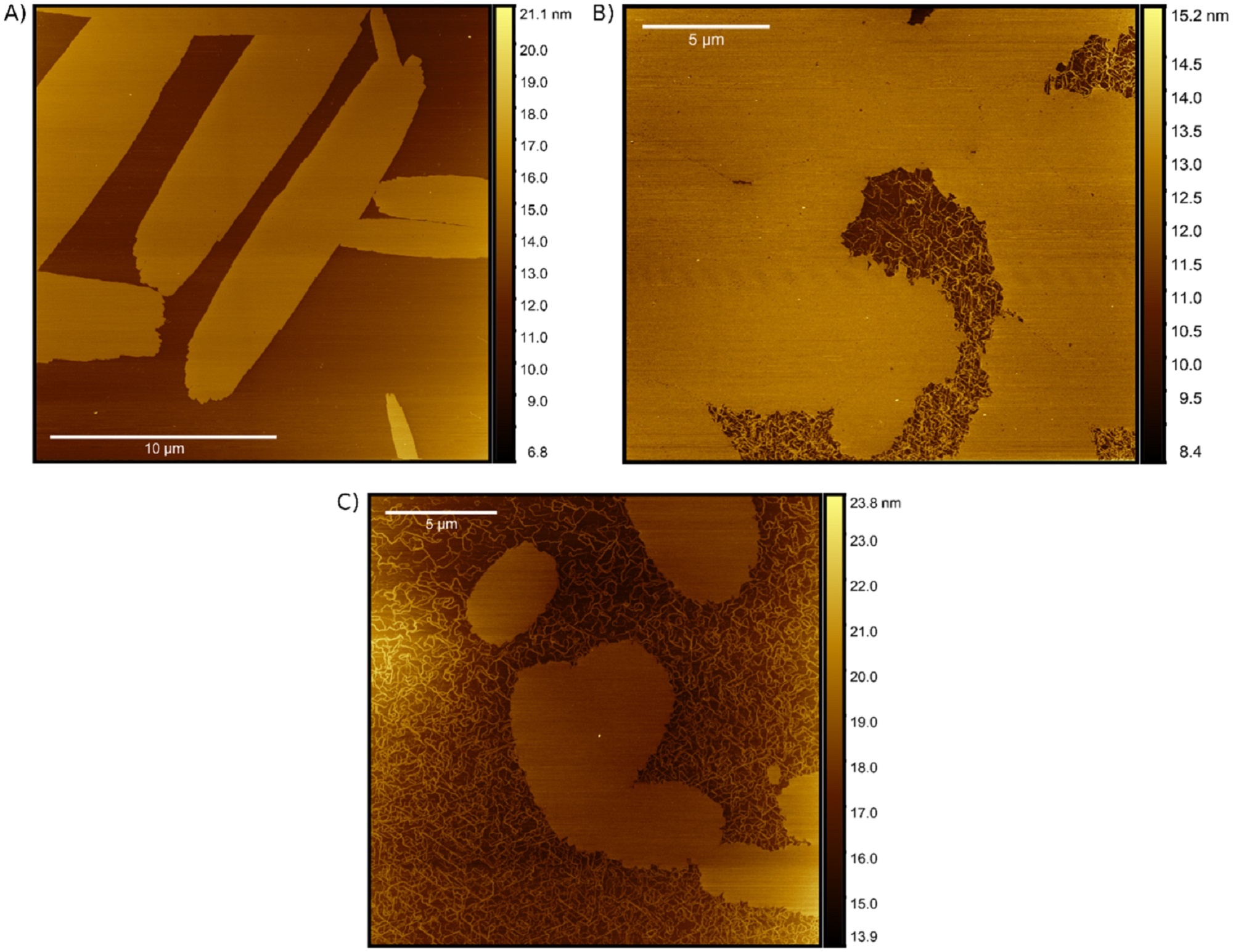
Figure 6 from Matthew Chiriboga et al. “Structural and optical variation of pseudoisocyanine aggregates nucleated on DNA substrates”:Atomic Force Microscopy visualisation of pseudoisocyanine aggregates – super aggregates (SA) nucleated on DNA substrates. AFM visualizations of pseudoisocyanine (PIC) aggregates formed in the (A) AT, (B) dsDNA, and (C) ssDNA nanostructures. Each of the samples was formed immediately before measurement by mixing 160 μM PIC dye with 500 nM DNA normalized to the dye-labeled strand concentration (i.e. 320-fold excess). When the SA was formed using an AT DX-tile template (figures 6(A) the authors observed the formation of large and long rod-like aggregates with a relatively isotropic growth axis. This supports the hypothesis proposed by Yoa et al which suggested aggregation along preferential axis due to a preferred interaction between the PIC and the mica NanoWorld USC-F0.3-k0.3 AFM probes were used for the under AC fast imaging mode in liquid.
Figure 6 from Matthew Chiriboga et al. “Structural and optical variation of pseudoisocyanine aggregates nucleated on DNA substrates”:
AFM visualization of SA formations. AFM visualizations of PIC aggregates formed in the (A) AT, (B) dsDNA, and (C) ssDNA nanostructures. Each of the samples was formed immediately before measurement by mixing 160 μM PIC dye with 500 nM DNA normalized to the dye-labeled strand concentration (i.e. 320-fold excess).

*Matthew Chiriboga, Christopher M Green, Divita Mathur, David A Hastman, Joseph S Melinger, Remi Veneziano, Igor L Medintz and Sebastián A Díaz
Structural and optical variation of pseudoisocyanine aggregates nucleated on DNA substrates
Methods and Applications in Fluorescence (2023) 11 014003
DOI: https://doi.org/10.1088/2050-6120/acb2b4

The article “Active self-assembly of piezoelectric biomolecular films via synergistic nanoconfinement and in-situ poling” by Matthew Chiriboga, Christopher M Green, Divita Mathur, David A Hastman, Joseph S Melinger, Remi Veneziano, Igor L Medintz and Sebastián A Díaz is licensed under a Creative Commons Attribution 4.0 International License, which permits use, sharing, adaptation, distribution and reproduction in any medium or format, as long as you give appropriate credit to the original author(s) and the source, provide a link to the Creative Commons license, and indicate if changes were made. The images or other third-party material in this article are included in the article’s Creative Commons license, unless indicated otherwise in a credit line to the material. If material is not included in the article’s Creative Commons license and your intended use is not permitted by statutory regulation or exceeds the permitted use, you will need to obtain permission directly from the copyright holder. To view a copy of this license, visit https://creativecommons.org/licenses/by/4.0/.

Real-time tracking of ionic nano-domains under shear flow

The behaviour of ions at solid–liquid interfaces underpins countless phenomena, from the conduction of nervous impulses to charge transfer in solar cells. In most cases, ions do not operate as isolated entities, but in conjunction with neighbouring ions and the surrounding solution. In aqueous solutions, recent studies suggest the existence of group dynamics through water-mediated clusters but results allowing direct tracking of ionic domains with atomic precision are scarce. *

Atomic force microscopy (AFM) can image single ions adsorbed at various solid–liquid interfaces. One of the main advantages of the technique is its ability to probe individual ions in-situ but with local contextual information about the interface over tens of nanometres at the point of measurement.*

High-speed atomic force microscopy (HS-AFM) operates similarly to standard AFM but with enhanced temporal resolution and can capture images at video rate, making it possible to track many molecular processes in real-time.*

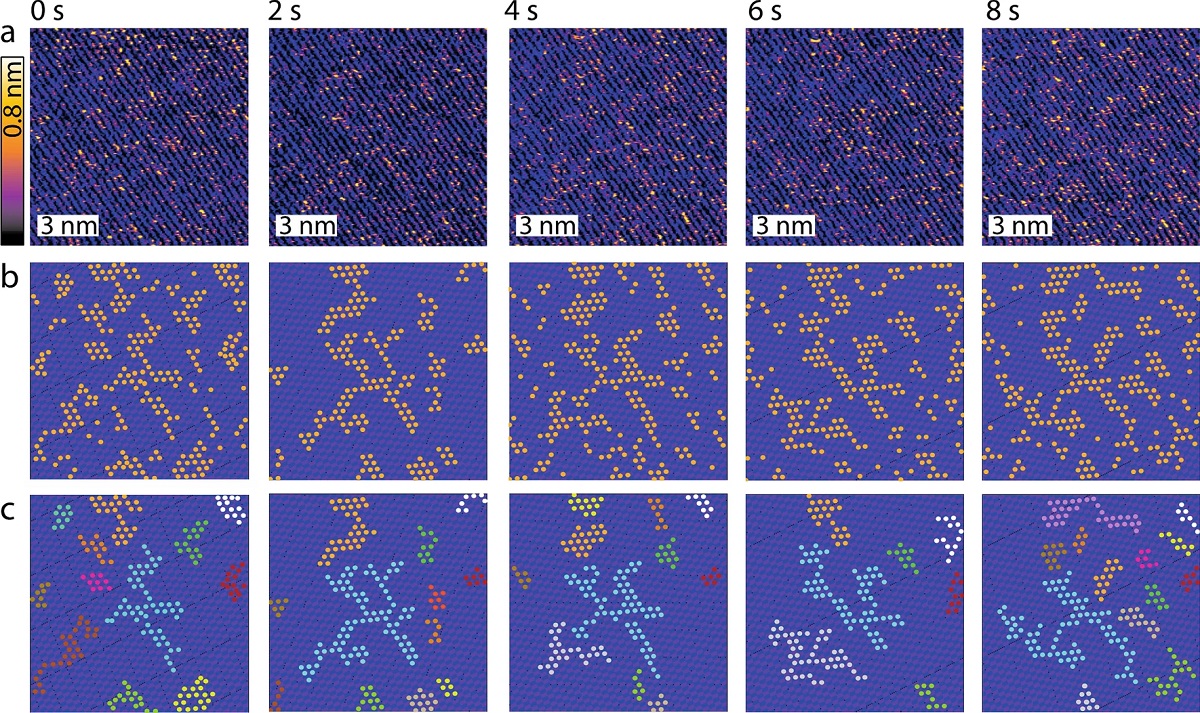
In the article “Real-time tracking of ionic nano-domains under shear flow” Clodomiro Cafolla and Kislon Voïtchovsky use high-speed atomic force microscopy to track the evolution of Rb+, K+, Na+ and Ca2+ nano-domains containing 20 to 120 ions adsorbed at the surface of mica in aqueous solution. The interface is exposed to a shear flow able to influence the lateral motion of single ions and clusters. *

They report the achievement of single-ion spatial resolution with ~ 2 s temporal resolution.*

During the measurements, the AFM cantilever and the sample were fully immersed in the aqueous ionic solution of interest. The AFM probes used were NanoWorld Arrow-UHF ultra-high frequency AFM cantilevers. *

The results presented in the article provide some quantitative insights into the relationship between single ion properties and group dynamics at the solid–liquid interface in the presence of a microscale shear flow, with potential technological applications from manufacturing biomedical devices to enhancing the performance of aqueous ion-batteries.*

Figure 1 from “Real-time tracking of ionic nano-domains under shear flow” by Clodomiro Cafolla and Kislon Voïtchovsky: Example of time evolution for adsorbed Rb+ ions at the mica-water interface in the presence of a shear flow. (a) A time-lapse sequence shows consecutive high-resolution HS-AFM topographical images of Rb+ ions at the interface between mica and a 5 mM RbCl aqueous solution. Rb+ ions appear as bright orange-yellow protrusions standing taller than the mica surface (purple-black). Periodic rows and larger domains are clearly visible as well as singly adsorbed rubidium ions. (b) Representative image analysis highlighting Rb+ ions as orange markers (obtained by thresholding) and the idealised underlying lattice derived by inverse Fourier transform of the filtered power spectrum in each image of (a) (see ESI Section 3 for details on the procedure). (c) The algorithm automatically associates neighbouring ions (within distances < 0.52 nm) to the same cluster. Domains smaller than 5 ions are discarded here. The different clusters derived in each image are highlighted using different colours, keeping for each cluster the same colour over time. The cyan-coloured cluster offers a good example of temporal evolution. The scale bars in (a–c) represent 3 nm and the z-scale in (a) corresponds to 0.8 nm. NanoWorld Arrow-UHF ultra-high speed AFM probes were used for the high-speed atomic force microscopy (HS-AFM).
Figure 1 from “Real-time tracking of ionic nano-domains under shear flow” by Clodomiro Cafolla and Kislon Voïtchovsky:
Example of time evolution for adsorbed Rb+ ions at the mica-water interface in the presence of a shear flow. (a) A time-lapse sequence shows consecutive high-resolution HS-AFM topographical images of Rb+ ions at the interface between mica and a 5 mM RbCl aqueous solution. Rb+ ions appear as bright orange-yellow protrusions standing taller than the mica surface (purple-black). Periodic rows and larger domains are clearly visible as well as singly adsorbed rubidium ions. (b) Representative image analysis highlighting Rb+ ions as orange markers (obtained by thresholding) and the idealised underlying lattice derived by inverse Fourier transform of the filtered power spectrum in each image of (a) (see ESI Section 3 for details on the procedure). (c) The algorithm automatically associates neighbouring ions (within distances < 0.52 nm) to the same cluster. Domains smaller than 5 ions are discarded here. The different clusters derived in each image are highlighted using different colours, keeping for each cluster the same colour over time. The cyan-coloured cluster offers a good example of temporal evolution. The scale bars in (a–c) represent 3 nm and the z-scale in (a) corresponds to 0.8 nm.

*Clodomiro Cafolla and Kislon Voïtchovsky
Real-time tracking of ionic nano-domains under shear flow
Nature Scientific Reports volume 11, Article number: 19540 (2021)
DOI: https://doi.org/10.1038/s41598-021-98137-y

Please follow this external link to read the full article: https://rdcu.be/cPRBu

Open Access The article “Real-time tracking of ionic nano-domains under shear flow” by Clodomiro Cafolla and Kislon Voïtchovsky is licensed under a Creative Commons Attribution 4.0 International License, which permits use, sharing, adaptation, distribution and reproduction in any medium or format, as long as you give appropriate credit to the original author(s) and the source, provide a link to the Creative Commons license, and indicate if changes were made. The images or other third party material in this article are included in the article’s Creative Commons license, unless indicated otherwise in a credit line to the material. If material is not included in the article’s Creative Commons license and your intended use is not permitted by statutory regulation or exceeds the permitted use, you will need to obtain permission directly from the copyright holder. To view a copy of this license, visit http://creativecommons.org/licenses/by/4.0/.

Actin filaments on Mica with APTES

Courtesy of Prof. Noriyuki Kodera, nanoLSI, Kanazawa University, Japan we could upload two new images and a very nice High Speed Atomic Force Microscopy (HS-AFM) video of Actin filaments on Mica with APTES to the image gallery and the video gallery on https://www.highspeedscanning.com/.

NanoWorld USC-F1.2-k0.15 Ultra-Short AFM cantilevers [C = 0.15 N/m; fo = 1200 kHz] were used for the high speed imaging.

HS-AFM Images of actin filaments on Mica with APTES. Buffer:100 mM KCl, 2 mM MgCl2, 1 mM EGTA, 20 mM Imidazole-HCl, pH7.6 (a) 250×250 nm2 and (b) 400×400 nm2. Image courtesy of Prof. Kodera, nanoLSI, Kanazawa University, Japan. NanoWorld USC-F1.2-k0.15 AFM probes from the Ultra-Short Cantilever (USC) series were used for the High Speed Atomic Force Microscopy
HS-AFM Images of actin filaments on Mica with APTES. Buffer:100 mM KCl, 2 mM MgCl2, 1 mM EGTA, 20 mM Imidazole-HCl, pH7.6 (a) 250×250 nm2 and (b) 400×400 nm2. Images courtesy of Prof. Kodera, nanoLSI, Kanazawa University, Japan. NanoWorld USC-F1.2-k0.15 AFM probes were used for the High Speed Atomic Force Microscopy

The HighSpeedScanning webpage is dedicated to presenting information about ultra high frequency AFM probe solutions for High Speed AFM ranging from already commercialized AFM probes such as the ArrowTM UHF and NanoWorld Ultra-Short Cantilever (USC) series to AFM probes that are still under development.

Additionally to the High-Speed AFM images and videos researchers worldwide kindly have provided us with so that we can share them with the whole High Speed AFM community you will also find  a list of links and references dedicated to High-Speed AFM on https://www.highspeedscanning.com/high-speed-scanning.html 

We are aware that these lists are far from complete and we are constantly working on keepting them up to date.  If your research institute or company is working with High Speed AFM (HS-AFM) using our AFM probes or if you have published articles with images that were achieved with our High Speed AFM probes annd you find that are missing from our list then please let us know via email: info@highspeedscanning.com if you would like us to add them to the list of references .